Summer wrap-up part 2 (The problem with shade)

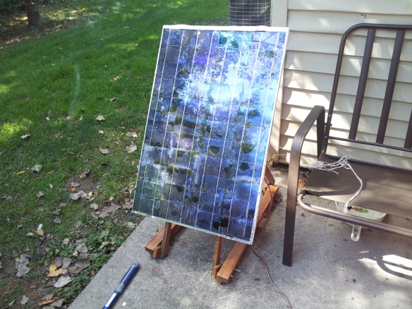
If you’ve noticed in the image of the solar panels in their natural habitat (my backyard) you’ll see that much of it is shaded.  This isn’t always the case, however it’s very much the case after mid-August once the sun has declined enough in the sky and the foliage from the trees is in its fullest bloom.

This presents a problem for those that might be in slightly more wooded areas that still would want to use the power of the sun to gather electricity.  So how does one get around that?

Cells could be mounted higher, certainly, but that might be an impossibility for land that’s surrounded by very tall trees.  Cells could be spread out to various sunny areas, but they’re not going to be efficient as they’ll most likely only be in sunny areas for part of the year.  Additionally, spreading them out means longer wires being run and an increase in power loss along this wiring.  Plus, solar panels get pretty gross over time and they need to be accessible enough to give a good cleaning.

So let’s make a solar panel that goes where the sun is. The concept goes like this:

  1. An array of batteries is stored in a housing, all of equal physical size and capacity
  2. A robotic arm takes a discharged battery out of the housing and places it on a mobile bot
  3. The robot navigates the land using GPS, radio communication to a central server, and various sonar/infrared sensors to avoid obstacles and find a nice sunny spot.
  4. It parks on the spot and deploys a solar panel to charge the battery it’s been assigned, along with its internal power source.
  5. Once charged, it navigates back home where the robotic arm takes the fully charged battery and places it back in the bank.
  6. It then loads another discharged battery onto the bot and the cycle repeats.

Seems simple enough, right?  Doesn’t seem economically practical at all unless the swarm of bots doing this is big enough.  Probably still isn’t a break-even point in there.  Don’t care, it’s neat.  So let’s get started.

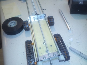
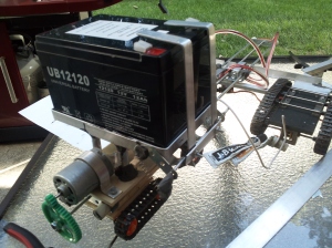
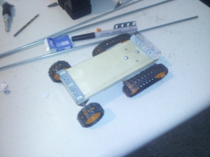
 This is the basic construct for a platform that will bear the weight of the battery.  It will not have a motorized drive-train as there would be a huge draw of power just bearing the weight of what is above it.  It’s made up of a few parts from a Tamiya Tracked Vehicle Chassis.  For this project I used a total of three of them.  They’re about $15 a pop on eBay.

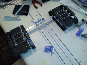
Through this base I run two 3/16″ smooth and one 1/8″ threaded rods.  This will connect to the drive trains and allow it to move closer and further from them, allowing the power of the chassis and the weight of the battery as an anchor to articulate the panel.


Here it is tied to the chassis, each of these have a drive train and motors attached.


A motor is attached to the back with gearing to turn the threaded rod which is held in place at the connection point to the drive train chassis, articulating back and forth respective to the circuit’s polarity.


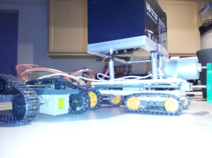
The wiring is snugged inside of some acrylic tubing and housed above to keep things nice and neat.  What isn’t pictured at this point is an additional drive-train attached to the front and mounting brackets for the panel.  Because I’m lazy and didn’t take any more pics.

The battery you’ll notice has securing brackets.  These are spring-loaded so that lifting the battery swings them away from the terminals and lowering the battery connects it to the terminals automatically.  Once complete, the system will detect a power-on with the connection of the battery, secure it with additional articulating power-driven latches (not pictured, but done) and run some self-tests.

Time to see how this thing handles the backyard terrain.  As I’m writing this I know the results of said tests but you’ll just have to wait until I get around to telling you about them.


Summer wrap-up part 1 (No more blues)

It’s that time of year where working outside is shortened in hours.  And the chill causes your nipples to pierce your shirt.  So much of my work space has been consolidated, but the projects are in full force.  Here’s an overall update and a promise to keep the posts more frequent and a little funnier.

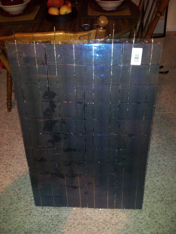
The solar panel succumbed to a nice blast of wind that sent it shattering.  The problem here was the construction more than the wind.  Without fully encapsulating the panels in an epoxy-like substrate they were subject to flex upon impact.  Being silicon-based and 0.2mm thick it doesn’t take much of a jar for them to shatter.  Trying to repair by removing the broken cells proved impossible as more and more kept cracking.  So time to redo:

As I’ve described the gist of how to put this together in a prior post I’ll skip the gruesome details.  The major difference here is that the panels are attached to glass, they’re closer together, and fully encapsulated with a clear-drying epoxy.  This makes them water-tight and gives them much more support.  Basically you can hit the thing and as long as you can’t shatter the glass, which is now also enforced with epoxy, you’re not going to hurt them.  The glass was unnecessary and I’d probably recommend doing it with plexi next time, but the glass was much cheaper.

As a result of the spacing changes and the dimension changes of the cells (4×5 with a single tab line to 3×6 with dual tabs) this panel is 25% smaller but still kicks out the same power of nearly 100 watts.  It has a short circuit voltage of approximately 25v.  This is an awkward voltage for a panel as they’re typically hovering around 12v, however there’s a reason for this.

The final wiring for the panel includes a high-power schottky diode that prevents any reverse voltage from frying the cells if their output dips below the voltage levels of anything they’re charging.  Basically it stops a battery it’s charging from discharging back into the panel once the sun goes away or the battery becomes fully charged.  This drops down the voltage by 0.9v.  The closed circuit voltage also naturally drops slightly leaving me with a little over 23v.  With this voltage I am able to split it into two voltages of 15v and 8v which are then used to charge 12v SLA batteries and sets of 3.65v Li-Ion batteries wired in series.  An interesting note about batteries is that even though they’re labeled with a specific voltage, they only run at that voltage for a specific instant in their discharge cycle.  12v batteries that are run through heavy deep-discharge cycles should be charged to 14.8v and discharged to approximately 11v.  Li-Ions should be charged to 4.2v and considered discharged at 3.2v for maximum life.  The speed of charge and discharge is also important and there’s a whole bunch of other crap that needs to be taken into account to maximize their health.  So I’ve implemented a software-based charger that monitors the batteries and optimizes their output.  So far it’s the only “ultra-smart” solar-based charger I’ve seen in existence.  Maybe it doesn’t even work.  Probably it’s a lot of extra overhead for something that’s not that important.  But I don’t care really, it’s neat.  More on that in future posts.

Also, the panel has to find the sun so it’s mounted to a make-shift rotating tracker that’s made out of scraps of an old desk (nothing greener than re-use):

That’s all for now.

Coming soon:

  • The problem with shade
  • The problem with wheels
  • Closing the feedback loop on CNC milling
  • Green garage gardening greatness
  • Zombie apocalypse weather preparedness
  • Watching the watchers

Yes, those are vague.  You’ll see.


No, I said I need some “juice”

One of the things I’ve noticed about electronic devices is that they all, unequivocally, run on electricity.  Microcontrollers and small motors and actuators and sensors and such are also fairly picky regarding the voltages they’re interested in using.  Primarily, microcontrollers require either 5V or 3.3V of power with very little tolerance away from their ideal supply.  The flow thus needs to be very regulated.

To do this efficiently a specialized power supply is often required.  Hobbyists with too much money at their disposal opt for bench supplies that have perfect little power nubs at different voltages and lots of fancy meters.

I don’t have too much money so I decided to see what I could do to make my own:

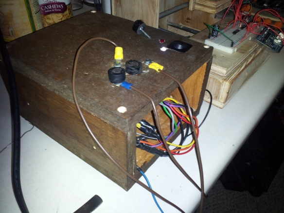
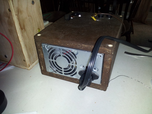
You’ll note that by checking out the back of it, it’s actually just an ATX power supply I’ve re-purposed from an old PC.  The wooden carriage for it is a few slabs cut from a desk that has long ago been retired.  One of those ones that you have to put together yourself alone in the dark of your apartment while you wonder about what might have been as you scrawl through useless misdirections and absent hardware.  The stain for the wood is called “Anything But Particle Board” and doesn’t match at all with the PCB mill I’m working on that’s positioned next to it.  The front piece isn’t attached yet, so the wiring is a little exposed at the moment.  Makes for a better picture/story.

The top of it has a power switch, a voltage supply indicator light, which is illuminated when the supply is able to maintain all regulated voltages given the current power draw on it.  It’s basically an “all is well” light.  Above that is a reset button, and to the left are 4 terminals, for 3.3V, 5V, 12V and ground.

A nice aspect of ATX supplies is that they are wired with a non-mechanical on/off feature that allows you to turn it on by sinking the power on one of it’s pins.  It also has a constant standby 5V output.  By grounding the power pin the supply is turned on with the switch I’ve installed.  By shorting that with the standby output, the reset button allows it to power down and restart.

Another bonus feature of the ATX supply is that it will cut off its voltage if it detects a short circuit or an unsafe draw of power.  This means that it will shut down as soon as it detects itself firing watt upon watt of electricity through your overweight, out of shape shell of forgotten dreams so that you can live another day to ponder the decisions in your life that led to this point.

The emperor’s new clothes

The Dremel is one of my favorite tools.  You can basically accomplish any cutting task with one if you’re patient enough or whatever.  Having recently upgraded to a much more powerful model I had the battery-powered model seen here kicking around.  Needing something capable of milling and etching for the CNC machine and not wanting to waste the expense to both my wallet and the environmental factors involved in shipping a DC motor overseas I decided to sacrifice the old model.

After disassembling, here’s what there is under the hood:


A hobby-grade DC motor with a chuck attached to it and rechargeable batteries.  Interestingly the batteries were advertised to have “Lithium Ion Technology” but they’re actually standard Ni-Cd batteries… the original rechargeables that have been around for about 30 years.  And suck.

The unit retailed for about $60… and the parts seen above can be purchased for about $8 total individually.  The rest is just injection-molded plastic.

So yeah, fisted.

Still love Dremel though…

Sleepless boys make all the toys

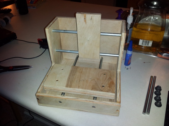
Not finishing projects is sort of my thing.  Finishing them and taking them apart when I’m done is also my thing.  But against all odds work as recommenced on the CNC mill.  Primarily because I really actually need it to get done so I can put it to work manufacturing parts for other projects.

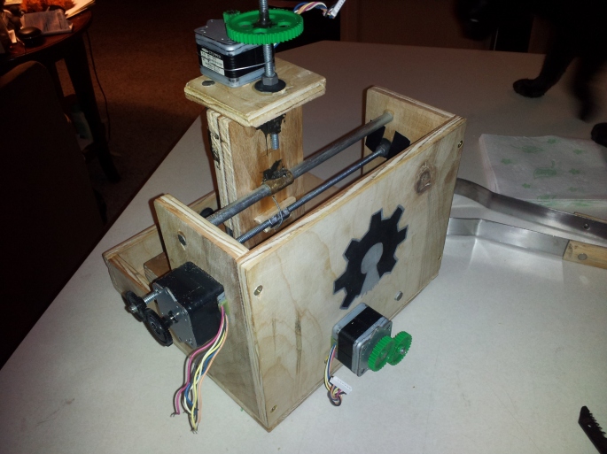
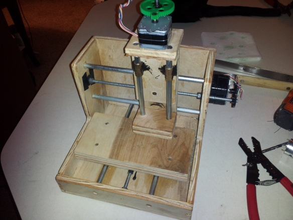
Now all three axis are running on balanced threaded rod, powered by three 1.8°/step stepper motors:

Back side with cat in background offering look of approval.

The z-axis has a ridiculous gear ratio to ensure that lifting the mechanism is pretty strain-free.

Each motor was tested, everything runs, and holy shit the thing is loud.  Some dampening will be needed but for a prototype, no complaints.  The motor is being readied for mounting.  It is a 6.2v motor that will be cranked up to 12-14v for a little extra rage.  Unfortunately, the actual area it has to work with is 7″x5″x1″, which isn’t huge.  But this is a proof of concept and if it works I’ll make one that’s much (much) larger.  A greater z-axis is  going to prove critical I suspect.

To actually run this, I have a few stepper motor drivers from Texas Instruments.  Or I might just make it run directly from a dozen or so transistors and some serious power switching that will be coupled with a computer’s USB port and special drivers (that I’ll have to make) to stream bits of data directly to shift registers.

Bedtime now though.

Blues for a solar panel

Oh noes!

One of the cells has split somewhat.  Apparently the strain of panels against plexiglass, which I have learned tends to expand and contract more than I would have expected due to temperature, has cracked it.  Being made of glass and <0.2mm thick, it’s not difficult to do.

The problem is that this single crack is limiting the output of this cell by ~30% of its output wattage.  That’s causing the entire panel to lose 30%.  Butts.

I’ll be repairing this.

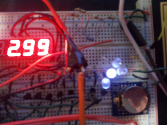
In the meantime, I noticed this at 11pm:

I stuck the above LEDs into the circuit to see what they were doing and to my surprise they were flickering right along.  But why flickering?  I started trying to figure out if there was any way there was an odd capacitance in the circuit that I wasn’t understanding.  But no, nothing.  Even with the MCU entirely powered down it was still happening.  And four LEDs drawing at least 20mA a piece wouldn’t be sustained by any capacitance.

What I did notice, however, was that the flickering matched the dancing of the flame of a tiki torch lit in the backyard that was near the panel.  3v and at least 80mA coming from a single torch in what would otherwise be pitch black.  Surprising…

More interesting to come, tomorrow though.

Things to look for soon:  Stirling engines, Peltier cell phone charger, my take on Mr Fusion.

Sidebar poll:

More maths

What you’re looking at is a case I’ve built to house the accelerometer module for the solar tracker.  It’s connected to the breadboard where the accelerometer itself was located yesterday.  I cut up a standard 6′ network cable and soldered it into a PCB along with the component.  Notice the distinct “North” label on the top of it.  This is absolutely critical in the calculations to ensure that the feedback the accelerometer provides coincides with the values that the MCU is expecting in order for the system to actually point directly at the sun.  This is a bit of an annoying downside of not using light detecting modules as sun-seekers.  It’s now dependent on perfect alignment with the azimuths.  This is, however, pretty manageable with either a hand compass or a compass module placed within the system.

Also, I discovered a slight cock-up with my maths from yesterday.  The Y-axis calculations are much simpler than I’d originally thought if I use the hour angle for the X-axis.  Then the Y-axis is simply the present latitude less the declination angle.  This isn’t a 100% accurate calculation, as it does not take altitude into account.  This is a pretty acceptable margin of error, however, in that it would take miles of altitude to have even a minute effect.

So I did a lot of calculations for nothing, really, is how it turns out.  Also my hour angle calculations weren’t taking DST into consideration, which was causing the expected X-axis angle of the sun to be off by 15°.

But that’s all fixed now and you’ll see the results here:

The Ideal X/Y values are positions the MCU expects the solar panel to be in to be staring directly into the sun.  The Actual X/Y are the values received from the accelerometer.  The reason for the deviation is because I’m just holding the thing to take a picture.  This feedback, however, will drive two DC motors that will manipulate the position of the panel.  Once I design it.  And the build it.

That’s all for now.

This is Sonny.  He’s awesome:

Here comes the sun

Our intelligence and our technology have given us the power to affect the climate. How will we use this power? Are we willing to tolerate ignorance and complacency in matters that affect the entire human family? Do we value short-term advantages above the welfare of the Earth? Or will we think on longer time scales, with concern for our children and our grandchildren, to understand and protect the complex life-support systems of our planet? The Earth is a tiny and fragile world. It needs to be cherished.

– Carl Sagan (1980)

By spending ~$25 and about 15 hours of research all issues that were previously blocking me from being able to calculate exactly where the sun would be on a given day and time have been completely resolved.

So let’s take a look at the mess that this triple-sized breadboard has become:
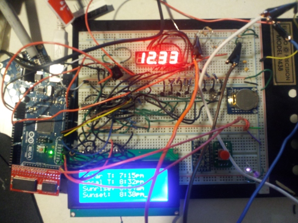
You’ll see a few new things on this board.  To the left, attached to the Arduino Mega 2560 is a memory expansion breakout board.  This ties directly in to what is unfortunately 40 pins of the board.  The good news is that 16 of them can be disabled and are accessible via headers on the expansion board.  Doing so disables half of the additional memory the board provides, so it must be used cautiously.  More on that later.  I haven’t soldered female headers into this yet as I don’t suspect I’ll need them.  Any additional sensor requirements can be driven from the available ADC pins.  Anything else can be handled through shift registers if necessary.

On the center right of the board, you’ll notice a button battery on a breakout PCB.  This is a real time clock module.  The battery serves as a method by which the 32.768MHz crystal can oscillate and maintain time when power is not supplied by the microcontroller (MCU).  It streams the time to the MCU and allows time accurate to +/- 1 sec/year to be used in all calculations without any external time source.

To the right of the LCD screen there are two other breakouts.  The right one is simply a 5-direction switch which will be used to navigate settings menus on the LCD screen once those are coded, so it isn’t being utilized at all.  The left one is a 3-axis accelerometer, which provides angle information relative to the earth.  This is also not wired at the moment, but will be shortly.  It will be used to measure the angle of the solar panel as it is actuated based upon the calculations the MCU provides.  Again, more on this in a bit.

MegaRAM Breakout
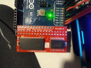
This is the breakout board purchased from [Rugged Circuits].  There are two chips on this circuit.  The right chip is a controller that manages communication between the RAM and the MCU.  The left chip is the actual RAM. It contains 128Kb of additional memory that is fully integrated into the MCU’s address tables.  Mostly.  Because the ATMega2560 uses 16 bit addresses, only the first 64Kb of memory is immediately addressable.  This includes the 8K of onboard memory as well.  By doing nothing but plugging this board in and setting a pin high to power it, 56Kb of additional memory is gained.  This leaves 72K unused.  Through the onboard controller and some manipulation of timing as well as very careful programming, the 72Kb can be accessed separately, broken out into several separate memory banks.  It’s a pain in the ass and unnecessary at the moment.  It also eliminates the possibility of using the 16 breakout pins.  Because I don’t need it at the moment and I would have to rework a great amount of code I’ve left the total memory at 64Kb (including the base 8K).  If I need more it’s there but for now it’s just hanging out laughing at the other RAM as it’s working its ass off.  What a dick.

RTC Module
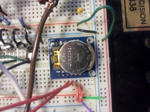
This is the RTC module that’s been touched on a bit already.  It has a two wire I2C serial interface with the MCU.  I2C is an interesting architecture because it allows 128 separate modules to be strung together through a 6-bit addressing scheme using only a data wire and a clock wire.  Well worth the sacrifice of two pins.  Also, these are two-way communication pins.  The time is settable and readable with some very simple wiring and commands.  This module, including shipping, cost a little over $5.  Why did I spend so much?  Because one excellent feature of this unit is that in addition to being able to manage accurate time through the year 2100, it also has 32Kb of EEPROM that can be read/written.  This will be very useful for saving state information relevant to battery charge cycles, sun tracking progress, etc should the unit lose power or be put into a low power standby during its cycle.  It can also help save some basic logging/debugging information as the system is built.  Before I’m done I’m sure I’ll put an SD card into the mix for some more interesting logging, but for now this will be a very nice to have.

Triple-Axis Accelerometer
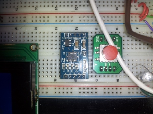
The module on the left is a triple-axis accelerometer (created by Virtuabotix [awesome people to deal with]).

This project only really requires two axis, so the X and Y will be the only ones wired.  But a bonus feature of this board is that it has a low-power mode that puts it to sleep when the MCU doesn’t need it.  Another interesting feature is free-fall detection.  If the board ever experiences zero G, it can set a free-fall pin to high in ~2ms.  Again, not needed for this project but probably pretty handy as a “hey by the way this whole thing you spent a lot of time on is hurtling towards the Earth at the exact speed Newton said it would…” alert.

Now to the maths…

Here are three shots which are simply values cycled through the LCD:

These are the 12 output values currently being calculated.  You’ll note the voltage, cell temperature, and power loss due to heat, which have been here for a while now.  Below those is the current date and time provided by the RTC.  This is what the rest of the calculations mean:

Solar T: This is the solar time.  It is the time that the photons currently hitting the earth left the sun, adjusted for the earth’s position in orbit, angle relative to its orbit around the sun and the sun’s wobble as it orbits the galaxy.  It’s also off by an additional hour because the sun doesn’t care about daylight savings time.

Local T: Local time, the current time at the MCU’s current place.  This is the same as the time provided by the RTC.

Sunrise/Sunset:  The sunrise and sunset times for the current day (adjusted for altitude, DST)

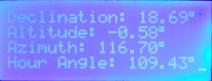
Declination: This is a value that fluctuates annually between 23.45°N at the Summer Solstice and 23.45°S at the Winter Solstice.  It is displayed here only as information as this value is already encapsulated in other values that are the ones we’re most interested in.

Altitude (Angle): This is how high in the sky the sun appears to be relative to the southern azimuth.  This will be a critical value in the final positioning but is also encompassed in another measurement.

Azimuth (Angle): This is how far from the southern azimuth the sun would appear to be if it were at ground level.  This is also critical, but also encompassed in other calculations.

Hour Angle: This is the angle of the sun from -90° to 90° as it moves across the sky throughout the day.  It is at -90° at sunrise and 90° at sunset.  Also a very critical value.

The position of the sun in the sky can be reflected with the hour angle serving as the X axis and the azimuth serving as the Y axis, inverted 90° out of phase.

The accelerometer will provide feedback on the panel’s position regardless of whether or not the panel’s mount is level on the ground.  This saves having to worry about the panel’s X-axis being perfectly aligned.  The Y-axis, however, can be an issue in that the panel’s mount must be perfectly aligned with the azimuth.  Also, the current latitude, longitude and altitude (relative to sea level) values are hard coded.  By adding GPS and compass modules, these values could also be computed, making the system entirely autonomous when it comes to seeking and harvesting light.

Time to build the mount.

And to throw in another Carl Sagan quote to complete the posting sandwich.

The neurochemistry of the brain is astonishingly busy, the circuitry of a machine more wonderful than any devised by humans. But there is no evidence that its functioning is due to anything more than the 1014 neural connections that build an elegant architecture of consciousness.

– Carl Sagan (1980)
Shave and a haircut (and native floating point support): 32 bits

Since the voting regarding which angle of attack to use on tackling the out of memory problem resulted in a tie I decided to take a half-of-each approach.  The code would be optimized as much as possible, but instead of dumping more RAM into the mix, I would set up a second microcontroller as a math co-processor.

I had a few right here to chose from.  Two PIC chips, two ATMega644P’s, a Sanguinololu (which another project already had dibs on unless I was guaranteed it could do the job, and two Parallax Propeller P8X32A QuickStart boards.

The Parallax Propeller is an interesting board.  It’s a 32-bit 8-core processor that supports development in C, C++, SPIN, and ASM.  Each core operates at a user-defined speed ranging from 20kHz to 80MHz (the k in kHz wasn’t a typo).  The 32-bit architecture also lent itself nicely to the floating-point arithmetic needed by the solar position calculations.  It also has 32kb of program memory and 32kb of RAM.

Here’s a picture of it as if that helps at all:

So I programmed it up and TADA! It was out of memory.  Because the fucker only allocates 4k per core and there’s nothing you can do to get at the rest.

Fuck.  So I bought a RAM upgrade for the original microcontroller.

$20 lighter.

This is the pre-optimized code in C++ for a 32 bit compiler if anyone has any ideas:

#include <Arduino.h>
#include "SolarPosition.h"
#include <Time.h>
#include <HardwareSerial.h>
int inputMonth;
 int inputDate;
 int inputYear;
 int inputHour;
 int inputMinute;
 int inputAMPM;
 double degreesToRadians = 3.1416 / 180.0;
 double radiansToDegrees = 180.0 / 3.1416;
 double feetToMeters = 1.0 / 3.28;
 double solarMinutesAfterMidnight;
SolarPosition::SolarPosition(){
 degreesToRadians = 3.1416 / 180.0000;
 radiansToDegrees = 180.0000 / 3.1416;
 feetToMeters = 1.0000 / 3.2800;
}
 double SolarPosition::getOutputEOT(){
 return outputEOT;
 }
 double SolarPosition::getSolarMinutesAfterMidnight(){
 return solarMinutesAfterMidnight;
 }
String SolarPosition::getOutputLSOT(){
 return outputLSOT;
 }
 String SolarPosition::getOutputClockTime(){
 return outputClockTime;
 }
 double SolarPosition::getOutputHourAngle(){
 return outputHourAngle;
 }
 double SolarPosition::getOutputAltitude(){
 return outputAltitude;
 }
 double SolarPosition::getOutputDeclination(){
 return outputDeclination;
 }
 String SolarPosition::getOutputSunrise(){
 return outputSunrise;
 }
 String SolarPosition::getOutputSunset(){
 return outputSunset;
 }
 double SolarPosition::getOutputAzimuth(){
 return outputAzimuth;
 }
 void SolarPosition::setTime(int Year, int Month, int Date, int Hour, int Minute, int AMPM){
 inputYear = Year;
 inputDate = Date;
 inputMonth = Month;
 inputHour = Hour;
 inputMinute = Minute;
 inputAMPM = AMPM;
 }
void SolarPosition::Calculate(int Year, int Month, int Date, int Hour, int Minute, int AMPM) {
 inputYear = Year;
 inputDate = Date;
 inputMonth = Month;
 inputHour = Hour;
 inputMinute = Minute;
 inputAMPM = AMPM;
 
 inputLongitude = 77.45;
 inputEastWest = 0; // West = 0, East = 1
 inputLatitude = 43.22;
 inputNorthSouth = 0; // North = 0, South = 1;
 inputElevation = 465;
 inputFeetMeters = 0; // Feet = 0, Meters = 1
 inputTimeZone = -5;
 inputDaylight = 1;
 inputZeroAzimuth = 0;// 0 = North, 1 = South

 if (inputEastWest == 1) inputLongitude *= -1; // [0] = east, [1] = west
 if (inputNorthSouth == 1) inputLatitude *= -1; // [0] = north, [1] = south

 if (inputMonth > 2) {
 inputMonth = inputMonth - 3;
 }
 else {
 inputYear = inputYear - 1;
 inputMonth = inputMonth + 9;
 }
 if (inputLongitude > 180) inputLongitude = inputLongitude - 360;
 if (inputLongitude < -180) inputLongitude = inputLongitude + 360;
 if (inputFeetMeters == 0) inputElevation *= feetToMeters;
int meridian = inputTimeZone * -15;
if (inputAMPM == 0 && inputHour == 12) inputHour = 0;
 if (inputAMPM == 1) { if (inputHour != 12) inputHour += 12; }
double inputHoursAfterMidnight = inputHour + (float)inputMinute / 60;
 double inputMinutesAfterMidnight = inputHour * 60 + inputMinute;
 double UT = inputHoursAfterMidnight - inputTimeZone - inputDaylight;
 double t = ((UT / 24) + inputDate + floor(30.6 * double(inputMonth) + 0.5) + floor(365.25 * double(inputYear - 1976)) - 8707.5) / 36525;
 double G = NormalizeTo360(357.528 + 35999.05 * t);
 double C = (1.915 * sin(G * degreesToRadians)) + (0.020 * sin(2.0 * G * degreesToRadians));
 double L = NormalizeTo360(280.460 + (36000.77 * t) + C);
 double alpha = L - 2.466 * sin(2.0 * L * degreesToRadians) + 0.053 * sin(4.0 * L * degreesToRadians);
 double GHA = NormalizeTo360(UT * 15 - 180 - C + L - alpha);
outputDeclination = atan(tan((23.4393 - 0.013 * t) * degreesToRadians) * sin(alpha * degreesToRadians)) * radiansToDegrees;
outputEOT = (L - C - alpha) / 15;
double clockTimeToLSOTAdjustment = ((inputLongitude - double(meridian)) / 15.0) - outputEOT + double(inputDaylight); // in hours
double solarHourAngle = NormalizeTo180(GHA - inputLongitude);
double apparentSolarTime = NormalizeTo24(12 + solarHourAngle / 15.0);
 
 solarMinutesAfterMidnight = inputMinutesAfterMidnight - (clockTimeToLSOTAdjustment * 60.0);
double whichDay = 0;
 
 if (solarMinutesAfterMidnight < 0)
 { 
 solarMinutesAfterMidnight += 24 * 60;
 whichDay = -1;
 }
if (solarMinutesAfterMidnight >= 24 * 60)
 { 
 solarMinutesAfterMidnight -= 24 * 60;
 whichDay = 1;
 }
 
 String solarTime = MinutesToClockTime(int(solarMinutesAfterMidnight));
if (whichDay == -1) outputLSOT = solarTime + "-";
 if (whichDay == 0) outputLSOT = solarTime;
 if (whichDay == 1) outputLSOT = solarTime + "+";
whichDay = 0;
if (inputMinutesAfterMidnight < 0)
 { // it's the day before
 inputMinutesAfterMidnight += 24 * 60;
 whichDay = -1;
 }
if (inputMinutesAfterMidnight >= 24 * 60)
 { // it's the next day
 inputMinutesAfterMidnight -= 24 * 60;
 whichDay = 1;
 }
String clockTime = MinutesToClockTime((int)inputMinutesAfterMidnight);
 
 if (whichDay == -1) outputClockTime = clockTime + "-";
 if (whichDay == 0) outputClockTime = clockTime;
 if (whichDay == 1) outputClockTime = clockTime + "+";*/
 
 outputHourAngle = (solarMinutesAfterMidnight - (12 * 60)) / 4;
 
 double altitudeAngle = radiansToDegrees * asin(
 (sin(inputLatitude * degreesToRadians) *
 sin(outputDeclination * degreesToRadians)) -
 (cos(inputLatitude * degreesToRadians) *
 cos(outputDeclination * degreesToRadians) *
 cos((solarHourAngle + 180) * degreesToRadians)));
outputAltitude = altitudeAngle;
 
 double preAzimuthAngle = radiansToDegrees * acos(
 (cos(outputDeclination * degreesToRadians) *
 ((cos(inputLatitude * degreesToRadians) *
 tan(outputDeclination * degreesToRadians)) +
 (sin(inputLatitude * degreesToRadians) *
 cos((solarHourAngle + 180) * degreesToRadians)))) /
 cos(altitudeAngle * degreesToRadians));
 
 outputAzimuth = preAzimuthAngle + (inputZeroAzimuth - 180);
 if (inputZeroAzimuth == 0)
 outputAzimuth = ChangeSign(outputAzimuth, 0, outputHourAngle);
 else
 outputAzimuth = ChangeSign(outputAzimuth, 1, outputHourAngle);
double sunRiseSetLSoTMinutes = radiansToDegrees * acos(-1 *
 (sin(inputLatitude * degreesToRadians) *
 sin(outputDeclination * degreesToRadians) -
 sin((-0.8333 - 0.0347 * sqrt(inputElevation)) * degreesToRadians)) /
 cos(inputLongitude * degreesToRadians) /
 cos(outputDeclination * degreesToRadians)) * 4;
 
 outputSunrise = MinutesToClockTime((int)(12 * 60 - sunRiseSetLSoTMinutes + (clockTimeToLSOTAdjustment * 60)));
 outputSunset = MinutesToClockTime((int)(12 * 60 + sunRiseSetLSoTMinutes + (clockTimeToLSOTAdjustment * 60)));
 
 }
double SolarPosition::ChangeSign (double input, int mode, double basis) {
if (mode == 0) {
 if ((input * basis) < 0) {
 input *= -1;
 }
 }
 
 else {
 if ((input * basis) > 0) {
 input *= -1;
 }
 }
 
 return input;
 }
String SolarPosition::doubleToString(double input,int decimalPlaces){
 if(decimalPlaces!=0){
 String string = String((int)(input*pow(10,decimalPlaces)));
 if(abs(input)<1){
 if(input>0)
 string = "0"+string;
 else if(input<0)
 string = string.substring(0,1)+"0"+string.substring(1);
 }
 return string.substring(0,string.length()-decimalPlaces)+"."+string.substring(string.length()-decimalPlaces);
 } else {
 return String((int)input);
 }
 }
String SolarPosition::MinutesToClockTime (int totalMinutes) {
 String output;
 int theHours = floor(totalMinutes / 60);
 int theMinutes = (totalMinutes % 60);
if (theMinutes < 10) output = "0" + String(theMinutes); // add leading "0" if necessary
 else output = String(theMinutes);
if (theHours < 12) {
 if (theHours == 0) theHours = 12;
 output = String(theHours) + ":" + output + "am";
 }
 else {
 if (theHours == 12) theHours = 24;
 output = (String(theHours - 12)) + ":" + output + "pm";
 }
 
 return output;
 }

 double SolarPosition::NormalizeTo360 (double theThing) {
 return (theThing - floor(theThing / 360.0) * 360);
 }

 double SolarPosition::NormalizeTo180 (double theThing) {
 theThing = NormalizeTo360(theThing);
 if (theThing > 180) { theThing = theThing - 360; }
return (theThing);
 }

 double SolarPosition::NormalizeTo24 (double theThing) {
 return (theThing - floor (theThing / 24.0) * 24);
 }